IoP - Bringing up the Irrigation Controller board
In the last article I talked about my motivation and some thoughts and design goals of the Irrigation Controller. In this article I will talk about bringing up the board for the first time - hardware- and software-wise.

In the last article I talked about my motivation and some thoughts and design goals of the Irrigation Controller. In this article I will talk about about bringing up the board for the first time.
The hardware
Many of my early projects taught me a lesson: don't populate all components of the board at once. Something will fail!
So, the first step was to populate the two switching power supplies of the board. Nothing more, nothing less. The first one's task is to power the main 3.3V rail of the board. It is always powered. Lo and behold, it worked in the first place!
The second switcher is normally turned off and will be enabled by the main controller, the ESP32. I didn't populate the logic around that yet, so the default of the switcher was to power up, too. This one is used for the auxiliary power to the relays and external sensors. It came up as well! The nominal voltage would have been 12V due to the relays, but I designed the switcher for ~10.4V to be able to provide power even when the controller will be powered by an nearly empty battery supply. 10.4V are enough to safely activate the relay coils.
Encouraged by this success, I went ahead and populated all other components. I decided to do this, because most parts are supporting stuff around the ESP32 itself, so I felt save populating it at once.
So, the time was right to connect the USB-to-UART bridge to the ESP32. The esptool did detect the device without a hitch! So I flashed some initial test code, which I developed on a simple breakout board before I even started to design the PCB. It came up as well!
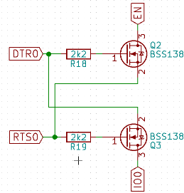
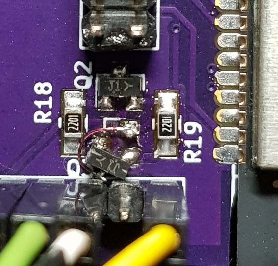
What didn't work auto as expected was the "auto programming" circuit, which is able to bring the ESP into programming mode and reset it. When entering the schematic, I missed the fact that one of the bipolar transistors (which I replaced with MOSFETs) was flipped in the original schematic. So I ended up with wrong Drain and Source connections. I spotted the error, because my reset and and prog buttons didn't work when the UART-bridge was connected. The solution was to rotate the FET by 45° and add a flying wire for the now landing-pad-less pin. Problem solved.
This is an excerpt from schematic showing the correct auto programming circuit:
And this is how I fixed it on the board:
There was another mistake on the board: The drill diameter of the footprint for the pluggable connectors was too small. I didn't read all of the recommendations in the datasheet. I ended up rasping the connectors' pins down. I did that because I didn't have a drill with the correct diameter at hand. It also saved the copper to connect the upper and lower layers within the holes/pads.
All hardware problems have been fixed in the schematic and layout - just in case I should need to order the PCB again. I am planning on posting the schematic and layout on github, but I need to clean some stuff up and come up with a fitting license. Update: The hardware repository is online.
And the software
My initial test code didn't have any means to test the IOs of the ESP32, so that got pretty urgent once the board was assembled. I implemented very basic getter and setter routines for the IOs. I can now call them with a serial command console on the debug and programming UART. The console is a modified and ported version of Elecia White's command console, which is released in the public domain. You can find her and the embedded.fm podcast at @logicalelegance. I can highly recommend the podcast when you are interested in embedded development!
With that code implemented I was able to test the relays and the shutdown-mechanism of the second switcher. Here's a screenshot of a short session in the command console:
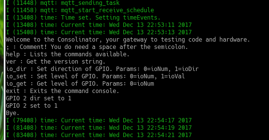
You can't see the commands I'm entering, because I missed to configure the terminal to send CR+LR instead of just the CR line ending. What I did was:
help
io_dir 2 1
io_set 2 1
exit
What you can see, is that I already got some MQTT test code in the build and a time keeping task, which gets the time from an NTP server.
Update: The software repository is online. It's also the main point of documentation for the project as a whole.
What's next
What's still missing to be tested are the two UART connections for external sensors. One of them will be connected to a fill level sensor that I'm currently building and trying to finish. The software is basically in place, but I need to finish the hardware and give it a test drive!
There's also an additional IDC connector bringing out an SPI interface. It has no planned use right now, but I wanted to be prepared to install additional sensors or other extension boards within the same enclosure as the main board. Obviously this hasn't been tested as well. I will do that when I have a use for the interface.